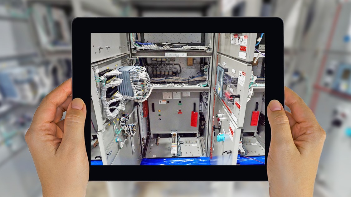
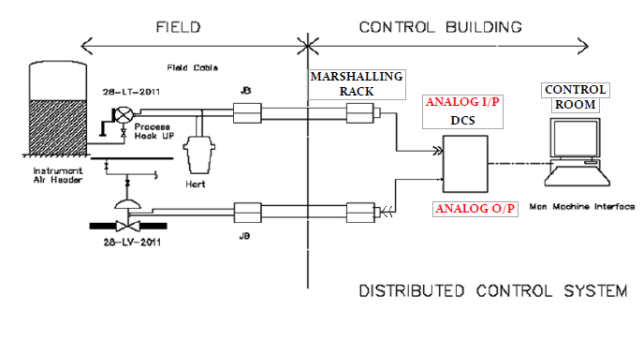
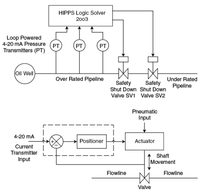
FAT (Factory Acceptance Test) is carried out in order to demonstrate that the system and its components function properly, that manufacturing, assembly, configuration and software generation are done correctly and that system performance is in compliance with the approved functional specifications and relevant documents. The same should be also carried out for DCS.
The main objective of the FAT are normally carried out during the final part of the design and engineering phase before the final installation in the plant. The FAT is a customized procedure to verify the instrumented safety system and the instrumented safety functions according to the specification of safety requirements.
Contents
The basic requirements of FAT
The test should be carried out with completely assembled system and complete I&C software performing all function expected out while in actual service.
Both computer code and technology programs to be installed and worked on the system until FAT.

Preliminary check
The FAT treatment shall be prepared by the supplier and sent well in advance before the beginning of the FAT for approval by the purchaser / consultant.
- General visual check and bill of materials check
- Construction check as per over all general arrangement drawings
- Dimensional check
- Labelling , terminal arrangement and equipment identification check
- Power supply voltage level check and power leeds-on check
- Cooling fan operation check
- Grounding network check
FAT Process at Distributed Control Systems
- Visual inspection
- Terminal arrangement and wiring check
- Power supply under voltage and over voltage check
- Verification of jumper settings
- Verification of healthiness of individual processors
- Verification of operator interface displays
- Verification of control functions: Start-up control, Acceleration control, Speed/Load control, Temperature control, Fired shutdown, Emergency shutdown
- Verify protection systems: over speed, over temperature, vibration, master protection, flame detection.
- System diagnostics
- Redundancy test for controllers
- Communication interface to DCS verification
FAT for Field Instrument
- Pressure indicators: Calibration Hydro test (1.5 times max. pr.)
- Pressure switches: Calibration test / Hydro test / Contact rating test / Accuracy test / Repeatability
- Differential pressure indicators: Calibration test / Hydro test / Leak test / Over range test / Accuracy test / Repeatability test.
- Differential pressure switches: Calibration test / Hydro test / Contact rating test / Leak test / Accuracy test / Repeatability test.
- Thermometers: Calibration / Material test / Accuracy test / Bore concentricity: + 5% of wall thickness / Hydrostatic test for TW (1.5 times max. pr.)
- Temperature switch: Calibration / Material test / Accuracy test / Bore concentricity: 1.5% of wall thickness / Hydrostatic test for TW (1.5 times max. pr.) / Contact rating test. Resistance temperature detector assembly. Calibration / Material test / Bore concentricity test / Insulation test (< 500 M at 500V DC) as per ISA, Hydro test for TW. Bore concentricity: + 5% of wall thickness, Accuracy test.
- Thermocouple assembly: Calibration / Material test, Insulation test (> 500 at 500 V, DC) as per ISA, Hydro static test (1.5 times max. pr.), Bore concentricity: + 5% of wall thickness.
- Thermo wells: Material test / Bore concentricity: + 5% of wall thickness / Hydrostatic test for TW (1.5 times max. pr.)
- Level gauges: Hydrostatic test / Material test / Seat leakage test / Ball check test.
- Level switches (Magnetic): Material test / Contact rating test / Hydro test / Calibration test.
- Flow switch: Material test / Hydro static test (1.5 times max. pr.) / function test.
- Flow glasses
- Variable area flow meters: Calibration test / Material test / Hydrostatic test (1.5 times max. pr.)
- Flow element: 100% Radiography test / Hydro test / Calibration test, IBR Certificate. Calibration test for flow element shall be witnessed by Purchaser/Consultant.
- Position transmitters
- Electro pneumatic converters: Calibration test / Accuracy test
- Solenoid valves: Hydro test / Seat leakage test / CV test / Coil insulation test
- Air filter regulators: Calibration test / Accuracy test
- Junction Boxes: Test for degree of protection / Material test
- Tests for terminal blocks: Test for molding for flame resistant, Non-hygroscopic and Decarbonized / Insulation test between terminals / Insulation between terminal block and frame.
- Thermocouple extension cable: Thermo-elf characteristic / Continuity test / Measurement on capacitance, inductance and loop resistance / Insulation resistance / High voltage test as per latest IS / Tensile and elongation test / Oxygen index test / Any other test applicable.
- Mass flow meter: Performance test / Calibration test / Hydrostatic test.
- Boiler Drum Level Gauge: Hydrostatic test / Material test / Seat leakage test / IBR Certificate
- Local Panels: Visual inspection, wiring & continuity check, H.V and I.R tests on panels, checking of bill of materials, functional tests.
Remote Factory Acceptance Test
If we have a team that has team members sitting in different locations in the world. Now they have to conduct testing that is involved in a logic test of the control system. Then control system vendor can offer a solution in which testing can be conducted by projecting the testing screen to every team member’s computer. Now to achieve this various control systems can offer various solutions. Some vendors have a virtual engineering platform with which they can seamlessly conduct the test.
Some vendors may offer through meeting tools like Cisco WebEx, Zoom, Microsoft Teams, etc. In such tools screen sharing of system takes place. This kind of testing is done in connection with remote desktop, team viewer, etc. But this type of testing has its own limitations. Because many open platform get involved. The secrecy of the testing gets compromised. Still, if you are using WebEx or Microsoft Teams then privacy is not that big issue but these are completely dependent on the screen sharing. The only presenter can interact with their screen.
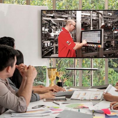
Now consider a scenario where the customer is testing a graphics with system vendor. Vendor’s is sharing system screen. Now control of the screen shall remain with the control system engineer. The testing engineer has to guide the control system engineer on what he wants to do. Even if he wants to check some navigation he has to rely on control system engineer. So the access of testing engineers is very limited in such a scenario.
Other than this there are other tools too which are specific to specific system vendors. In such a tool, testing engineers can also interact with the screen. These are more convenient to use and gives more confidence and comfort to the testing engineers.
Many control system vendors provide such a platform which includes Honeywell, Emerson, etc. They also use these platforms for virtual or cloud engineering without the requirement of actual hardware and can simulate all the logic without the requirement of hardware. The same platform are used for the testing to give a feel that the complete team is testing in one place but obviously it takes more internet bandwidth and requires a good internet connection.
Now, if these FAT are so convenient then why some people avoid them. So some people are not very comfortable with the idea of team members sitting in different locations. There can be some other reasons too. What do you people think? Why organizations avoid this way of doing FATs? Feel free to let us know.


 Tiếng Việt