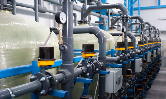
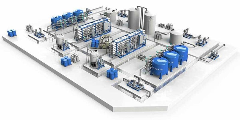
While laboratory analytical measurements are required to establish the proper treatment process in the water treatment plant, process control systems and on-line analytical instruments have been developed to assist the treatment plant operator in the control of the treatment process. Process automation can be separated into 2 types – continuous (or analog), and sequential (or logical). Flow control is an example of continuous or analog control, while the sequencing of valves in the backwash of a filter is logical control.
Originally, SCADA, Supervisory Control And Data Acquisition, referred to the system of remote control of pumping systems for raw water supply and distribution of treated water. The term SCADA finds common usage in reference to the entire treatment process automation and control system control system and the remote control system.
Well sites and remote raw water pump stations, sometimes referred to as low service pump stations, are monitored and controlled from plant facilities that communicate to the remote site via licensed and license-free radio systems, cellular phone systems, leased and dial-up phone systems, and most recently, via the Internet. The SCADA system controls the sequencing and speed of pumps, and maintains run-time logs for maintenance scheduling. Modern water treatment plant process automation and control systems require ease of secure communication over wide areas.
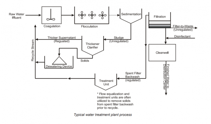
The process automation and control system measures and controls the flow of the raw water supply into the plant. It provides a master signal for proper dosing, or pacing, of pre-treatment chemicals. A properly designed control system monitors the inventory of stored chemicals. One of the critical processes in the treatment of potable water is the filtration process, or more importantly, the proper backwash of the filter media. Poor control of the backwash sequence can lead to loss of filter media, shortened filter run times, and boils and turbidity breakthroughs.
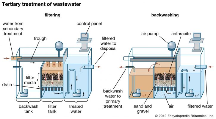
Automatic filter backwash control provides a consistent process of cleaning, and in the case of multimedia filters, proper re-stratification of the media. Air-water backwash control is extremely critical. An automatic backwash control system provides all interlocks to control the pumps, blowers and valves to provide a safe and reliable operation. In some cases, the automatic control system is designed to adjust the backwash flow rate based on temperature or viscosity of the water, and terminate the backwash sequence based on time or the turbidity of the backwash water.
The process automation and control system provides post treatment pacing signals and provides inventory data for finished water, backwash water and water used in-plant. The plant automation system can also calculate and record clearwell contact time data required by federal and state regulatory agencies.
Contents
The Water Treatment Process
Various treatment methods are available for making water safe and appealing to the consumer. The methods used depend primarily on the characteristics of the raw water. Surface water sources require more extensive treatment because they are exposed to industrial, domestic, and aquatic life and wild animal contamination. Water treatment combines a variety of chemical, mechanical and hydraulic processes.
The water treatment process from raw water supply to the pumping of treated water into the distribution system can be divided into 4 main categories:
Preliminary treatment, Pre-treatment, Filtration and Post-Chemical Treatment.
Preliminary Treatment
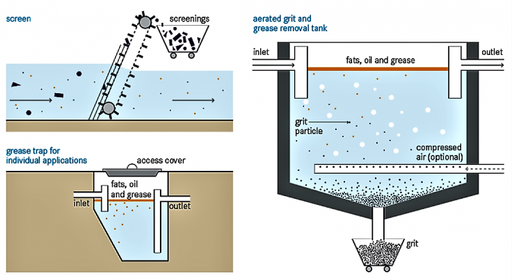
Preliminary treatment reduces the load on treatment process by removing some of the impurities from the raw water supply and alters some of its objectionable characteristics.
Head loss measurement across the screening and micro-straining equipment provides information for proper cleaning of the screening devices. In addition to chemical treatment for algae control, many treatment plants are now faced with the problem of zebra mussels growing on the intake structures. The injection of chemicals at the intake structure is one of the methods used to control their growth and attachment to the intake piping.
Raw water flow measurement is made somewhere near the upper end of the water treatment plant to control the flow rate at each treatment process, adjust chemical feed rates, determine pump efficiency and power requirements, and calculate detention times. Venturi flow meters, in combination with accurate differential pressure transmitters, are most commonly used in water treatment plants due to their ability to handle large volumes of water and their low permanent head loss. The raw water flow measurement and control system determines the amount of water to be treated. Water treatment plants are designed so that the flow of water through the plant from pre-treatment to post-treatment is by gravity flow.
Pre-sedimentation is generally used where streams, rivers and lakes provide the raw water supply. Large amounts of suspended solids can be present seasonally when lakes “turn over” in the spring and winter, and during periods of high flows in streams and rivers.
| Preliminary Treatment | |
| Screening | Screening of large debris and aquatic life protects plant equipment. |
| Chemical Treatment | Algae are generally controlled through the addition of copper sulfate. |
| Pre-sedimentation | This process removes sand, silt and other gritty materials, which can damage plant equipment. |
| Micro-straining | Removes small debris, algae and other aquatic plants. |
Pre-Treatment
Pre-treatment processes are designed to remove suspended solids from the raw water supply after it has gone through preliminary treatment. They reduce the load on the filtration process. Where the water supply is from ground water sources, a softening process can be used at this point.
The aeration process brings water in close contact to air either through a bubbling process or by cascading thin sheets of the water through the air or over packing in stripping columns. Stripping columns now find wide spread use where ground water has been contaminated by industrial cleaning solvents. The aeration process is designed to remove dissolved gases or volatile organic chemicals. Injection of powdered carbon is used in some pre-treatment of surface water to adsorb chemical contaminants.
The coagulation and flocculation processes are required to remove suspended solids that are too small to be removed in the sedimentation process. Suspended particles usually carry a negative electrical charge, and tend to repel each other. Analytical instruments have been integrated into process control systems to assist the operator in the proper dosage of alum, one of the most commonly used coagulants to neutralize the negatively charged particles and promote the formation of floc. Floc is formed when microfloc particles collide and stick together to form settleable particles. The introduction of automatic control of the alum feeders has produced significant chemical cost savings and reduced the loads in the filtration process.
Sedimentation and clarification processes are designed to settle suspended solids in rectangular, circular or conical shaped basins. Tube settlers and plates are used in some shallow basins to reduce the flow velocity and promote settling of the suspended solids.
| Pre-Treatment | |
| Aeration | Removes troublesome gases, oxidizes metallic impurities |
| Coagulation/ Flocculation | Helps remove non-settleable solids. |
| Sedimentation/ Clarification | Removes solids to decrease the loading on the filtration system. |
Filtration
Two types of filtration processes are commonly used – gravity filters and pressure filters. The filtration processes are similar, except the pressure filtration takes place in a closed cylindrical steel tank, either vertical or horizontal. Both filtration systems use sand or sand/anthracite multi-media as the filtering media. Some smaller pressure filter systems use diatomaceous earth as the filter media.
There are variations of filter systems available, including “package” systems. However, the following description refers to a typical gravity filter system in a moderate-scale to large-scale water treatment plant. The general operating characteristics of the filter process systems are identical.
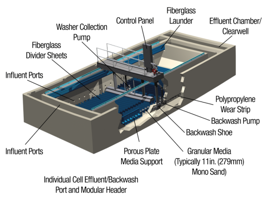
Gravity filters are large concrete bays containing an underdrain system to support the filter media and to evenly distribute backwash water. “U” shaped wash-water troughs are placed above the media to collect and carry away backwash water. Auxiliary cleaning is done through a surface scour system called agitators, surface wash or “sweeps.” One of the newer developments of auxiliary cleaning makes use of introducing air into the backwash water. All filters have either five or six valves associated with the filter bay, depending on the type of backwash procedure that is used, and whether or not the local regulatory agency requires a “filter-to-waste” step following completion of the backwash sequence.
The control valves associated with a filter are influent, effluent, drain and backwash. The fifth valve is either an agitator water supply valve or an air valve, depending on whether a surface agitator wash system or an air/water system is used.
The sixth valve is the “filter-to-waste” valve. Some states require that prior to returning a filter to the filtration mode following a backwash, the filtered water must be discarded to waste to prevent filtered water with turbidity spikes from entering the clearwell.
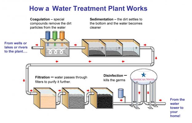
In the filtration mode, treated water enters the filter box through influent piping or channel and fills the box. Water flow is down through the media, through the underdrain support system and out through the effluent piping where flow is measured and controlled by a rate-of-flow controller. The rate-or-flow controller is commonly a venturi meter, a flow transmitter and a filter effluent valve. As the loss-of-head across the filter increases, the filter effluent valve must modulate to a more open position to maintain the setpoint of the flow. Filtered water flows through the rate-of-flow-controller to the “clearwell.”
The filter media used in a filter is commonly thought to trap the suspended materials. However, filtration is a combination of both physical and chemical mechanisms. As water passes through the media, large particles are trapped, and suspended particles become stuck to the surface of the grains of filter media and to other particles previously adsorbed by the media. Filter run time is dependent on how many particles are present in the water supply to the filter, and the initial cleanliness of the filter following the backwash sequence. Run times can vary from as short as 15 hours or less to over 100 hours. In the filtration mode, grains of filter media tend to stick together forming “mudballs” because of sticky floc. Unless backwashing removes this material, mudballs can sink into the media and clog the filter.
As the filtration process progresses, the filter media becomes more restrictive to flow, causing an increased head-loss through the media. If allowed to progress too far, negative pressures can be produced in the effluent piping that can cause air binding. A “loss-of-head” transmitter is a transmitter that senses the differential pressure between the head of water in the filter bay and the pressure in the effluent piping. In an automatic backwash system, high loss-of-head is one of the signals used to alarm or start a backwash sequence.
Backwash Sequence
There are three types of backwash procedures currently in use – manual, automatic and semi-automatic.
In the manual mode, an operator manually operates all valves and pump start/stops in sequence. In the automatic mode, all sequencing is done by the control system. The backwash procedure is started automatically after the control system receives a high loss-of-head alarm, a high turbidity alarm, or a preset filter run-time has been reached. In the semi-automatic mode, the operator initiates the automatic backwash sequence following a high loss-of-head alarm, a high turbidity alarm, or a preset filter run-time has been reached.
The procedure for a typical air/water backwash sequence with filter-to-waste in a sand/anthracite multi-media filter is as follows:
1. Close the influent valve.
2. Check for the influent valve “closed” limit switch signal.
3. Start alarm timer for “closed” limit switch signal.
- Alarm on time out. Stop backwash sequence.
- Reset alarm timer on receipt of limit switch signal.
4. Draw down the filter level to a preset level above the media.
5. Check for the level switch signal.
6. Close the effluent valve.
7. Check for the effluent valve “closed” limit switch signal.
8. Open the drain valve.
9. Check for the drain valve “open” limit switch signal.
10. Start alarm timer for “open” limit switch signal.
- Alarm on time out. Stop backwash sequence.
- Reset alarm timer on receipt of limit switch signal.
11. Start the air blower.
12. Check for blower start (discharge pressure switch)
13. Open the air scour valve.
14. Check for air scour valve “open” limit switch signal.
15. Start alarm timer for “open” limit switch signal.
- Alarm on time out. Stop backwash sequence.
- Reset alarm timer on receipt of limit switch signal.
16. Start the backwash pump.
17. Check for pump start (discharge pressure switch)
18. Modulate backwash valve open to preset low rate flow.
19. Stop blower when filter level reaches preset level below bottom of wash troughs.
20. Close air scour valve
21. Check for air scour valve “closed” limit switch.
22. Start alarm timer for “closed” limit switch signal.
- Alarm on time out. Stop backwash sequence.
- Reset alarm timer on receipt of limit switch signal
23. Ramp backwash flow rate to preset high rate.
24. Time backwash to preset time or monitor turbidity of backwash water in drain.
25. Ramp backwash rate down at preset rate to promote re-stratification of the filter media.
26. Close backwash valve.
27. Check for backwash valve “closed” limit switch.
28. Start alarm timer for “closed” limit switch signal.
- Alarm on time out. Stop backwash sequence.
- Reset alarm timer on receipt of limit switch signal
29. Stop backwash pump.
30. Close drain valve.
31. Check for drain valve “closed” limit switch.
32. Start alarm timer for “closed” limit switch signal.
- Alarm on time out. Stop backwash sequence.
- Reset alarm timer on receipt of limit switch signal
33. Open influent valve.
34. Check for preset level in filter.
35. Modulate filter-to-waste valve though filter flow controller.
36. Time filter-to-waste (or monitor effluent turbidity).
37. Close filter-to waste valve.
38. Check for filter-to-waste valve “closed” limit switch signal.
39. Start alarm timer for “closed” limit switch signal.
- Alarm on time out. Stop backwash sequence.
- Reset alarm timer on receipt of limit switch signal
40. Activate effluent valve control through rate-offlow controller.
Butterfly valves with electric motor operated actuators are commonly used in the on/off and modulating control for gravity filters. They typically are set to operate from full open to full closed, or full closed to full open in one to two minutes. Monitoring the activation of the valve limit switch serves both operating and safety functions. Alarm timers are set to alert the operator if the valve limit switch is not activated in a preset time period during the backwash sequence.
The process automation and control system measures, controls, totalizes and sums the individual filter effluent flows to determine the amount of post treatment chemicals required.
The control of the valve sequences, the safety checks, the proper ramping up and down of the for backwash flow rates, and the control of the filterto-waste create difficult procedures for an operator to perform manually. The total time for performing a backwash can take 30 minutes or more. Programmable logic controllers (PLC) are excellent devices for on/off control but are difficult to integrate into a process automation and control system that requires modulating control, flow integration and totalization and archiving of real-time and historical data. Distributed control systems provide excellent control capabilities and data handling, but do not provide ladder logic programming capabilities for ease of sequence control.
Recently, digital control equipment was introduced that combines the best features of the distributed process control with those of the programmable logic controller. This hybrid process automation controller is programmable in five different languages – ladder logic, function block, sequential function chart, structured text and instruction list – which meets the requirements of a new international programming standard, IEC-61131.
Programming is implemented using graphical programming. Using graphical programming, languages can be mixed. For example, ladder logic can be used to turn pumps on and off, combined with function blocks to modulate valves or integrate and totalize flows. Backwash sequencing can be programmed using the sequential function chart.
An enhanced software version adds the features of preprogrammed function blocks, alarm capabilities, and real-time and historical data archiving. The system also serves as a web server for internet access, particularly useful for monitoring remote sites, or secure access into the plant control system.
Post Treatment
Filtered water is referred to as treated water. It requires disinfection in the post-treatment process. The most commonly used chemical for disinfection is chlorine. The amount of chlorine to be injected is determined by the total filtered water flow, the amount of water being pumped into the distribution system from the clearwell, and the amount of contact time required as the filtered water passes through the clearwell. Contact time is determined as a function of the flow velocity through the clearwell (time), the water pH, its temperature and the amount of residual chlorine required for safe drinking water.
Optional post treatment includes adsorption through the use of granular activated carbon (GAC) for taste and odor control, fluoridation and stabilization.
Depending on the raw water source, the water may contain amounts of dissolved organic substances. Organic substances can be partially removed by chemicals used to oxidize the compounds. However, granular activated carbon and synthetic resins are most commonly used to adsorb these organic substances. GAC contactors are similar to filters, except the media is granular activated carbon. Contactors are backwashed in a similar fashion to filters to remove trapped solids. However, the activated carbon must be periodically regenerated in high temperature furnaces to remove the adsorbed chemicals.
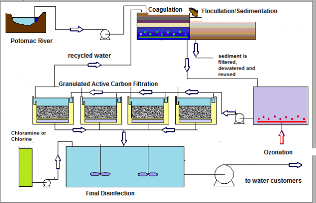
Fluoridation is used to maintain levels of fluoride in the drinking water known to prevent tooth decay. Fluoride is added to the treated water after filtration but before disinfection. Too little fluoride can be ineffective in preventing tooth decay. However too much can cause tooth discoloration or serious pitting.
The injection of stabilization chemical is used to control the corrosive and scale-forming characteristics of water before it enters the distribution system and, ultimately, the consumers’ piping systems. Lead and cadmium are two metals most likely to cause problems. Lead solder was used to join copper pipes in household plumbing. Cadmium was a constituent of galvanized pipes. Corrosion of cast iron mains can cause formation of iron deposits that protect bacteria from the disinfection effects of residual chlorine.
Since corrosion attacks the pipe surface, many of the chemicals used provide a protective coating. Chemicals commonly used for the stabilization of drinking water include lime, sodium carbonate (soda ash), sodium bicarbonate, and polyphosphates.
Following post treatment of the treated water, it is called finished water. The process automation and control system serves an important function in the disinfection, fluoridation and stabilization processes in analyzing and controlling the feed rates, and keeping records of the current inventory of chemicals, the feed rates, and the quantity, the pH and the alkalinity of the finished water.
Conclusion
Process automation and control systems serve a vital role in the safe and reliable operation of a water treatment plant in providing safe drinking water. Used properly, they are useful tools for lab technicians and plant operators, for maintenance scheduling and for management.
For the lab technician, analytical instrument readings can be used for control of various chemical feeders. The process automation and control system has the capability to perform repetitive calculations and store the results in useful database formats to meet regulatory agency requirements.
For the plant operator, the process automation and control system is a useful tool for tedious, repetitive operations. The filter backwash procedure requires constant monitoring of valve positions and flow rates to guarantee clean properly re-stratified filter media. The process automation and control system, in
combination with level and weighing devices, keeps track of chemical inventories.
For plant maintenance scheduling, the process automation and control system will keep track of the run times of all operating equipment. It can alert maintenance personnel when scheduled maintenance needs to be performed. The system can serve to keep track of spare parts and consumables.
As a management tool, the process automation and control system will keep track of production data and treatment costs. It is vitally important that the system supplier have process knowledge, the hardware, the software, the service and the experience to furnish a process automation and control system for safe, reliable water treatment plant operations.
CTI SUPPLY – Automation System Integrator
We provide designing and programming services for automation systems. CTI SUPPLY has years of experience implementing industrial automation solutions utilizing PLCs. We are capable of developing new PLC systems from the ground up and also troubleshoot, update, maintain and add up to pre-existing PLC systems. Our engineers have hands-on experience in working in multinational corporations, high-tech automated manufacturing plants, the water treatment and the oil and gas industry. Are you looking for a system integrator with lower expense on programming cost and better service? Contact us.


 Tiếng Việt